





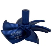

Robot gripper design is the process of matching a gripper to one part and one motion. You define the part's weight, size, and surface first. Then you choose how the jaws move, how the fingers hold, and how much force the grip needs. Next comes the actuator, the fingers, and the mount. Last, you test for slip before the gripper goes into production.
This guide covers that process in eight steps. It includes the force math, pneumatic sizing, and finger rules we use when we build grippers for CNC machines. It works for a gripper on a robot arm and for a gripper that runs inside a machining center with no arm at all. Every number below can be checked against your own part.
What Robot Gripper Design Covers
A robot gripper is the end effector that grasps, holds, and releases a part. It is one type of end-of-arm tooling (EOAT). Gripper design happens at two levels. Level one is building the mechanism: actuator, drive, jaws, and housing. Level two is designing the fingers, mount, and controls around a gripper body you buy.
Most machine shops work at level two, and they should. A commercial gripper body has years of seal, bearing, and cycle testing behind it. Your engineering time pays back faster in the fingers, because the fingers are the only part of the system that touches the workpiece. If you need the basics on gripper types and prices first, our robot gripper guide covers them.

The Four Ways a Gripper Can Hold a Part
Gripper engineers sort every holding method into four groups. The standard engineering reference on robot grippers uses these terms, and they are worth knowing because product literature often mixes them up.
| Holding method | How it holds the part | Examples | Typical use |
|---|---|---|---|
| Impactive | Jaws press directly on the part | Parallel, angular, and 3-jaw grippers | Machined parts and most industrial handling |
| Ingressive | Pins or needles go into the surface | Needle grippers | Textiles, composites, foam |
| Astrictive | A field creates the holding force | Vacuum cups, magnets, electroadhesion | Sheet metal, flat parts, steel parts |
| Contigutive | The surface sticks to the part | Adhesive and freeze grippers | Light, niche parts |
Magnetic and vacuum grippers still touch the part. The field does the holding, but the cup or pole face is in contact. This guide focuses on impactive grippers, the jaw-type designs that handle most machined parts, and every step that follows builds on that choice.
The Robot Gripper Design Process in 8 Steps
How do you design a robot gripper? Follow these eight steps in order. Each step produces something the next one needs.
- Define the part. Record weight, size range, material, finish, and center of gravity. Output: a part spec.
- Define the motion. Note peak acceleration, orientation changes, cycle time, and clearance at pick and place. Output: a motion profile.
- Choose the grip strategy. Decide between shaped fingers that cradle the part and flat fingers that rely on friction. Output: a finger concept.
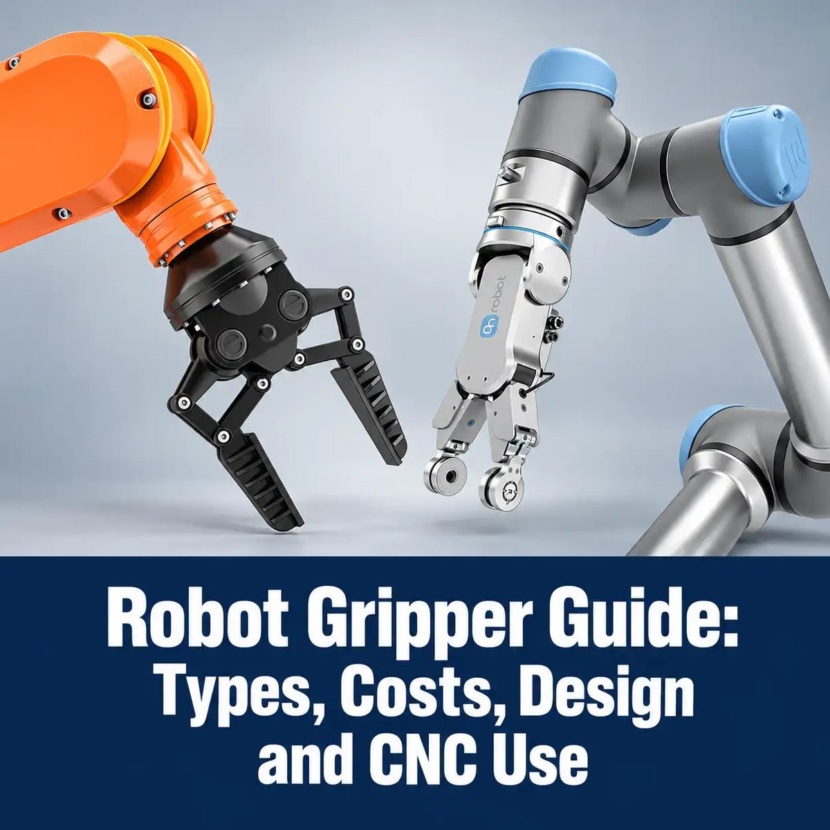
- Choose jaw motion and jaw count. Pick parallel, angular, or 3-jaw concentric. Output: a gripper style.
- Calculate grip force and check moments. Size force with a safety margin and confirm finger length is inside the gripper's limits. Output: a force and finger length requirement.
- Select the actuator. Choose air, electric, hydraulic, or vacuum. Output: a gripper model or shortlist.
- Design the fingers, mount, and sensors. Output: finger drawings, an adapter plate, and an I/O list.
- Prototype and test. Run slip, repeatability, and air-loss tests on real parts. Output: a go or no-go for production.
Skip a step and it shows up later as a dropped part. The first two steps decide everything after them.
Steps 1 and 2: Start With the Part and the Motion
Write down the part before you sketch anything. A gripper designed around a guess fails on the first part that doesn't match the guess.
| Part property | What to record | Why it matters |
|---|---|---|
| Weight | Heaviest part in the family | Sets grip force |
| Size range | Smallest and largest grip dimension | Sets jaw stroke |
| Material and finish | Aluminum, steel, plastic; machined, cast, or coated | Sets friction and marking risk |
| Center of gravity | Distance from the grip point | Sets moment load on the jaws |
| Shape | Square, round, thin wall, irregular | Sets jaw style and finger shape |
| Condition at pickup | Dry, oily, coolant-wet, chips | Changes friction |
The motion matters as much as the part. A part that moves slowly in a straight line needs much less grip than one swung around a robot wrist at full speed. Record the peak acceleration and deceleration. Note any rotation that turns the part on its side, because that changes which way the load pulls on the fingers. Leave clearance at pick and release too, since fingers that clip a fixture will knock parts loose.
Parts coming off a CNC machine add one condition most guides skip. They are usually wet with coolant, and they sometimes carry chips. Coolant lowers friction between finger and part, and chips pack into finger pockets. Design for a wet, dirty part from day one. Good results in a dry bench test then become a bonus, not a false promise.
With the part and motion on paper, the next decision is how the fingers will actually hold it.
Step 3: Choose a Grip Strategy: Form-Fit vs Friction Grip
There are two ways to keep a part in the fingers, and the choice changes how much force you need.
- Friction grip (force-fit). Flat fingers squeeze the part and friction holds it. One finger set covers a wide range of sizes. It also needs the most force, and it is the first to fail when parts are oily or wet.
- Form-fit grip. The fingers are shaped to the part with a V-groove, a pocket, or a ledge under it. Finger geometry carries the load instead of friction. Required force drops, and the part stays put under hard acceleration. The cost is flexibility, since a pocketed finger usually fits one part family.
- Combined grip. Most good industrial fingers mix both. A ledge or pocket takes the load in the main direction of travel, and friction handles the rest.
How big is the difference? In an ideal symmetric model, a round part held in 90-degree V-groove fingers can get about 1.4 times the friction hold of flat fingers at the same jaw closing force, for loading along the groove axis. That means roughly 30% less jaw closing force in that model. A V-groove alone is not positive retention along its axis; a ledge or shoulder is needed to support that direction geometrically. A ledge under the part does even better in the vertical direction, because it carries the part's weight with no help from friction at all.

The same logic applies to inside gripping. Fingers that open into a bore can be stepped so the part rests on a shoulder instead of hanging on friction.
Shaped fingers are the cheapest grip force you will ever buy. Once you know the strategy, the next choice is the jaw motion that delivers it.
Step 4: Jaw Motion and Robot Gripper Mechanism Design
Robot grippers move their jaws in one of three ways: in a straight line, through an arc, or toward a common center.
| Jaw motion | How the jaws move | Best for | Watch for |
|---|---|---|---|
| Parallel | Straight line, faces stay square to the part | Square and rectangular parts, most machined stock | Stroke limits the size range |
| Angular | Jaws pivot through an arc | Tight vertical space, one part size | Grip point shifts as the jaws swing |
| Concentric (3-jaw) | Three jaws close on one center | Round and cylindrical parts | Shorter stroke |
Most machine tending runs on parallel grippers. The jaw faces stay square to the part, the part lands on the same centerline every cycle, and finger design stays simple. Angular grippers earn a place where there is little room above the part. They usually suit one part size, and long jaws swinging through a wide arc build up inertia at the end of the stroke.

Two Jaws, Three Jaws, or Four Contact Points
Part shape decides the jaw count. Two jaws handle flat and square parts, which covers most machining stock. Three jaws center round parts on their axis. Handling a family of similar round parts in two jaws? A double-V finger gives four contact points and keeps each part on the jaw centerline. Multi-finger hands that copy a human hand belong in research labs and humanoid robots. They are rarely the right answer for loading a machine.
Drive Mechanisms Inside the Gripper
Between the actuator and the jaws sits a drive mechanism. It decides how force, stroke, and speed trade against each other.
- Wedge or cam. A piston pushes a wedge that drives both jaws at once. High force, short stroke, compact body. Common in pneumatic parallel grippers.
- Rack and pinion. A gear ties the two jaw racks together so they move in sync. Longer stroke and smooth motion, with less force for the size.
- Toggle linkage. Force climbs sharply as the linkage straightens near the end of travel. A design with a verified over-center lock or mechanical latch can hold without continuous input force. A linkage near its straight position is not automatically self-locking.
- Lead screw. Common in electric grippers. Some lead-screw designs resist back-driving. Power-off retention depends on screw geometry, friction, vibration, and any brake; verify it for the selected model.
Fully Actuated vs Underactuated Designs
A gripper's degrees of freedom (DOF) tell you how many independent motions it has. For a flat linkage, engineers count them with the Gruebler-Kutzbach equation:
M = 3(n − 1) − 2j₁ − j₂
Here n is the number of links including the frame, j₁ is full joints such as pins and sliders, and j₂ is half joints. A four-bar finger linkage has 4 links and 4 pin joints, so M = 3(3) − 8 = 1. One actuator drives it.
A fully actuated gripper has an independent actuator for each controlled degree of freedom. A one-DOF finger mechanism can therefore follow a constrained path with one actuator. An underactuated gripper has fewer actuators than degrees of freedom. Passive joints, springs, or linkages let its fingers adapt to a part. That can help with mixed shapes; stiffness, positioning, and contact behavior still need validation for CNC loading.
Jaw motion and mechanism give the gripper its character. Force decides whether it can actually do the job.
Step 5: Calculate Grip Force (With a Worked Example)
Most dropped parts trace back to this step. The math is simple, but the inputs need care.
The Grip Force Formula
For an equal-load friction grip lifting vertically, with acceleration acting in the same direction as the gravity load, each jaw needs:
Required force per jaw · vertical friction-grip model
Fjaw = m × (g + a) × S ÷ (n × μ)
| Symbol | Meaning |
|---|---|
| m | Part mass (part weight = m × g) |
| g | Gravity, 9.81 m/s² (32.2 ft/s²) |
| a | Upward acceleration, or equivalent downward-load deceleration, for this vertical model (m/s²) |
| S | Safety factor |
| n | Number of jaws in contact with the part |
| μ | Coefficient of friction between finger and part |
This scalar formula is a starting model, not a general robot-motion calculation. For sideways motion, rotation, unequal contacts, or an offset center of gravity, resolve the forces and moments at the contacts. Use consistent units: kg and m/s² give newtons; the worked example below uses part weight in lbf with dimensionless multipliers.
Two details trip people up. First, spec sheets list force two ways: per jaw, or the total of all jaws. Read the note under the force table before you compare models. Second, published grip force is measured at a stated finger length and pressure, and it drops as the grip point moves farther from the jaw.
Where the "10 to 20 Times Part Weight" Rule Comes From
Pneumatic gripper manufacturers publish a shortcut: pick a gripper whose force is 10 to 20 times the part weight. The rule is just the formula above with three inputs filled in. It assumes two jaws and friction between 0.1 and 0.2. It also uses a safety margin of 4 to cover the shocks of normal transport.
- With μ = 0.2: F_jaw = W × 4 ÷ (2 × 0.2) = 10 × W
- With μ = 0.1: F_jaw = W × 4 ÷ (2 × 0.1) = 20 × W
For fast moves, a 30 to 50 times part-weight band can be used as a preliminary screen. It is not a universal rating or a substitute for the selected manufacturer’s dynamic load calculation.
Why use friction values that low? Clean, dry steel on aluminum is usually well above 0.2. The low numbers cover the real conditions on a shop floor: cutting oil, coolant film, and surface finish that changes from lot to lot. Use them unless you have measured your own.
Worked Example: A 4 lb Part
| Case | Calculation | Force per jaw |
|---|---|---|
| 4 lb (1.8 kg) aluminum block, flat steel fingers, clean and dry (μ 0.2) | 4 × 4 ÷ (2 × 0.2) | 40 lbf (178 N) |
| Same block, coolant-wet (μ 0.1) | 4 × 4 ÷ (2 × 0.1) | 80 lbf (356 N) |
| Same block, fast moves or hard stops (30 to 50 × W) | 4 × 30 to 4 × 50 | 120 to 200 lbf (534 to 890 N) |
| 4 lb round bar in 90-degree V-groove fingers, normal moves | (40 to 80) ÷ 1.41 | 28 to 57 lbf (126 to 252 N) |
Look at the last row. The same weight needs about 30% less force once the fingers are shaped to the part. If you know your arm's actual peak acceleration, plug it in as a instead of leaning on the multiplier bands.
Check Moments and Finger Length
Grip force multiplied by the distance from the jaw to the grip point is a moment, and the jaw guides carry all of it. A jaw pushing 40 lbf at a grip point 2 in. from the jaw face puts 80 in-lbf on the guides. Stretch the finger to 4 in. and it doubles to 160 in-lbf. Add the part's weight acting on an offset center of gravity, plus acceleration, and long fingers wear out guides fast.

Every gripper maker publishes a chart of allowable grip point distance at each pressure. Stay inside it. Keep the part close to the gripper body, and keep fingers light: aluminum over steel unless wear says otherwise.
With a force number in hand, the actuator choice becomes a shortlist instead of a guess.
Step 6: Pick the Actuator
Five actuator types cover nearly every gripper. Here is how they compare on the points that matter for design.
Pneumatic
Electric (servo or stepper)
Hydraulic
Vacuum
Soft (fluidic)
For machined parts the choice usually narrows to air or electric. Air wins on force per pound and on price. Electric wins when force or jaw position has to change from one part to the next, or when there is no clean air at the robot. Most CNC grippers run on air, so the next section goes deeper there.
Pneumatic Robot Gripper Design
Pneumatic robot gripper design starts with one formula: force equals pressure times piston area.
Bore Size and Pressure Set the Force
Piston force before mechanism ratio and losses
F = P × A
A 20 mm (0.79 in.) bore at 87 psi (0.6 MPa) has a piston area of about 0.49 in². That gives roughly 42 lbf (188 N) of piston force. The drive mechanism then changes that number. A wedge multiplies it, long levers reduce it, and seal friction takes a few percent. Once you have a model in mind, use its force curves instead of hand math, because those curves already include the losses.
Size for the lowest pressure the gripper will actually see. If shop air sags to 80 psi when the compressor cycles and three machines blow off at once, the gripper has to hold at 80. After that, the regulator becomes your force control. Drop pressure for thin-wall parts that would distort. Raise it for heavy blanks. That adjustability is a big reason most CNC pneumatic grippers run on plain shop air.
Single-Acting, Double-Acting, and Spring-Assisted
- Double-acting. Air closes the jaws and air opens them. Powered motion in both directions; opening and closing forces can differ.
- Single-acting. Air drives one direction and a spring returns the jaws. One port and simpler plumbing, but the spring uses up part of the force.
- Spring-assisted double-acting. Air works both ways, and a spring adds grip force. A correctly sized closing spring can retain the part if air drops; verify its remaining force at the actual grip opening.
A gripper's resting state without air is called normally open or normally closed. That choice matters most during an air loss.
Designing for Air Loss
Air drops. A hose splits, a fitting backs out, a compressor trips. Decide now what the gripper does with the part when it happens. There are three common design answers:
- Spring assist. A closing spring can keep the jaws on the part without air if its force is sufficient for the load and grip opening.
- Pilot-operated check valves. They trap air in the cylinder when supply pressure drops. They hold well at first, but trapped air can leak down over time.
- A self-locking mechanism. A verified over-center linkage or mechanical latch can hold position without continuous input force.
Then prove it. Step 8 includes an air-loss test for exactly this reason.
Valves, Flow Controls, and Sensors
- Valve choice. A single-solenoid 5/2 valve shifts back when electrical power drops. A bistable double-solenoid 5/2 valve typically retains its last state when electrical power is removed; confirm the model. A closed-center 5/3 valve blocks both cylinder ports in its center position, but leakage and air compressibility remain. None of these valve arrangements alone guarantees safe load retention.
- Flow controls. A meter-out flow control on the exhaust slows jaw closing, which protects delicate parts and finished surfaces.
- Jaw sensors. Magnetic switches can confirm set jaw positions. To distinguish a held part from an empty close, use a separate part-present sensor or a position sensor with enough resolution to detect the expected grip opening.
Air sets the force. The fingers decide whether that force actually holds the part.
Step 7: Design the Fingers
Fingers are where a custom design earns its keep. The gripper body is a commodity. The fingers are specific to your part, and they decide whether it stays put.
Finger Materials
| Material | Strengths | Limits |
|---|---|---|
| Aluminum (6061, 7075) | Light, fast to machine, keeps moment loads low | Wears faster on steel parts |
| Steel (4140, hardened inserts) | Wear resistance on steel parts and rough castings | Heavier, adds moment load |
| Plastics (acetal, nylon) | Won't mark finished surfaces | Less stiff, can creep under load |
| Urethane or rubber pads | Raise friction and conform to small shape errors | Wear out; check coolant compatibility |
Finger Geometry Rules
- Wrap the part. Contact enough of it to stop movement in both directions across the jaws.
- Cut lead-in chamfers. The part self-centers when the pick is slightly off.
- Avoid wedging. Steep, narrow grooves can jam the part so it won't release. Most designers keep V-grooves at 90 degrees or wider for round parts.
- Check clearance through the full stroke. Fingers must clear the fixture at pick and the next fixture at release.
- Keep fingers short and light. Step 5 showed what extra length does to the guides.
- Give chips somewhere to go. Blind pockets fill with chips and coolant. Add relief cuts or through-slots.
- Make fingers fast to swap. Two dowel pins and two screws locate a finger the same way every time.
Machinists already know the best trick here. Treat gripper fingers like soft jaws on a vise: start from a blank and machine the fingers to the part on your own CNC. You get a true form-fit for the cost of a short program.
Short, shaped, and quick to swap: get the fingers right and the gripper holds. On a robot arm, the next job is fitting it all to the wrist.
Robot Arm Gripper Design: Mounting, Payload, and Integration
Robot arm gripper design adds one constraint a machine-mounted gripper never faces: the gripper is one load among several on the wrist. The arm doesn't care which pound came from where.
Mounting
Most industrial robots use a tool flange bolt pattern defined by ISO 9409-1. An adapter plate connects the flange to the gripper. Every millimeter that plate adds moves the load farther from the wrist. A tool changer adds weight and length too, so it only earns its place if you actually change grippers.
Payload Budget
The arm's rated payload has to cover everything past the flange: gripper, fingers, adapter plate, tool changer, and part. Take a 5 kg (11 lb) arm carrying a 1.2 kg gripper plus 0.3 kg of fingers and plate. That leaves 3.5 kg (7.7 lb) for the part, before you check the offset. Then compare the load and its center-of-gravity offset against the arm's load chart. Gripper weight is the line item people forget.
Routing, Controls, and Sensing
Route air lines and cables through or along the wrist with strain relief, and confirm wrist rotation won't wind them up. A pneumatic gripper fires from a digital output to a solenoid valve. Electric grippers connect through digital I/O, a fieldbus, or IO-Link. Add jaw position sensing on every gripper and part-present sensing where a missed pick would crash something.
Arm-mounted design comes down to weight and leverage. The environment adds the next set of rules.
Designing for Safety and Harsh Environments
Safety Under ISO 10218:2025
ISO 10218, the main industrial robot safety standard, was revised and published in two parts in February 2025. Part 2 addresses robot applications and cells, including collaborative applications and end-effector integration. For gripper design, the practical result is clear: the gripper, the fingers, and the part all belong in the risk assessment.
Expect the assessment to look at grip retention on air or power loss and at pinch points between fingers. Rounded finger edges matter too, along with force limits wherever people share the workspace. Work through them with whoever signs off on the cell's risk assessment.
Coolant, Chips, and Washdown
This is the paragraph most gripper design guides leave out, and it is where grippers in machine shops actually wear out. Coolant works past weak seals. Chips pack into jaw slides and finger pockets. For any gripper working in or near a CNC enclosure:
- Choose sealed jaw guides or guides with wipers.
- Blow off the part and fingers before closing on a part.
- Add drain paths so coolant doesn't pool in the fingers.
- Use corrosion-resistant fasteners on everything that gets wet.
- Eliminate blind pockets that trap chips.
A design that works dry on the bench is half done. Testing proves the other half.
Step 8: Test and Validate the Design
| Test | How to run it | Pass when |
|---|---|---|
| Full-stroke function | Cycle open and closed, empty and then with a part | No binding, consistent timing |
| Repeatability | Pick and place the same part 50 or more times and measure where it lands | Inside the fixture's tolerance |
| Grip force at the grip point | Force gauge between the fingers at real finger length | Meets the Step 5 number at minimum air pressure |
| Slip test | Worst-case part, wet if it will be wet, at full program speed | Zero movement in the fingers |
| Air or power loss | Cut supply while holding a part | Part stays put, or releases exactly as designed |
| Endurance run | A full shift or more of continuous cycles | No drift, leaks, or finger wear |
Fix the first failure before you test anything else. A part that slips at full speed usually needs better finger shape, not more pressure. More pressure marks parts and wears guides. Better shape fixes the cause.
Testing ends the engineering. One question is worth asking before any of it starts: does this job need a custom design at all?
Simple Robot Gripper Design: Where to Start a Prototype
A simple robot gripper design uses one actuator and two fingers. That is enough to learn every principle in this guide.
Three starting points work well:
- Servo parallel gripper. One hobby servo drives a gear pair or a rack and pinion that moves two fingers in a straight line.
- One-servo claw. One finger is fixed and the other rides on the servo horn. Angular motion, and the easiest build there is.
- Air-powered soft gripper. Cast silicone fingers with internal channels curl when inflated. A common classroom project.
A 3D printed body in a rigid plastic plus soft pads in a flexible material makes a working prototype in an afternoon.
Be clear about what a simple design leaves out. It has no force feedback, no fail-safe, no rated wear life, and no protection from coolant. That is fine for learning and for light pick-and-place. It is not fine for loading a CNC machine that runs unattended overnight.
Build or Buy: When to Design Your Own Gripper
| Situation | Design the whole gripper | Buy a body, design the fingers |
|---|---|---|
| No catalog gripper fits the part or the space | ✓ | |
| Special sensing, such as tactile or in-process gauging | ✓ | |
| Research, education, or low cycle counts | ✓ | |
| Square or round machined parts | ✓ | |
| Production uptime and spare parts matter | ✓ | |
| Cycle counts in the millions | ✓ |
Our position is simple. For machined parts, design the fingers, not the mechanism. A commercial gripper body's seals, guides, and cycle ratings took years of testing to prove. Your design hours go further in the fingers, the mount, and the test plan.
Gripper Design Without a Robot Arm: CNC Spindle Grippers
Not every gripper needs an arm. A spindle gripper sits in a CNC machine's tool changer like a cutting tool. The machine calls it with a tool change, moves it with its own axes, and opens or closes the jaws with an M-code. The machine does the moving. The gripper does the holding.
That changes the design problem. There is no robot-arm payload to budget and no robot program to write. The spindle, tool changer, and machine axes still have load and moment limits. The constraints come from the machine instead.

Design Constraints Inside a Machining Center
- Fit the tool changer. The gripper's diameter, length, and weight must fall inside the machine's limits for a tool pocket. Check the machine manual.
- Use the air the machine already has. Through-spindle air (TSA) or through-spindle coolant (TSC) can close the jaws. Machines without either need another air path.
- Survive the cutting environment. Coolant and chips are everywhere inside the enclosure.
- Fit the control. The gripper runs on M-codes inside the part program.
How GimGripper4™ Meets Them
- One tool slot. Stored in the tool changer and works with almost all tool changers.
- Machine air or coolant. Normally open fingers close on through-spindle air. Coolant versions close on TSC, and FloLink™ versions serve machines without either.
- Validate air-loss retention. Confirm how the selected GimGripper4™ configuration retains the actual part, then test it at the production grip opening and load.
- Grip range 0 to 4.125 in. Parts under 10 lb on standard models, under 40 lb on high force models.
- ±0.001 in. repeatability on the TSA model, at 0 to 175 psi.
- Rated to 2,000,000 actuations, with service every 250,000 cycles.
- Holders: CAT40, BT40, BT30, and HSK.
- Fingers: mount on FastFinger™ plates. A plate and finger set ships with every spindle gripper package. A spare universal gripper plate kit keeps a second part family ready to swap.
Steps 1 through 8 still apply. The part spec, grip strategy, force check, finger design, and testing all carry over. What drops out is the arm, its payload budget, and its program.
A robot arm is still the better design in some cases. Pick an arm for parts heavier than a spindle gripper's rating or for one robot serving several machines. An arm also makes sense for deburring or washing between operations, and for picking unsorted parts from a bin. For single-machine loading of parts that fit, CNC spindle grippers remove the arm from the design entirely.
Apply the design to CNC machine tending
Explore CNC spindle grippers
Compare configurations for your machine, part, and available air or coolant supply.
Shop CNC Spindle GrippersCommon Robot Gripper Design Mistakes
- Sizing force for a part sitting still. Fix: include acceleration and moments, then check the manufacturer’s dynamic limits.
- Running long fingers with no moment check. Fix: stay inside the maker's grip point distance chart.
- Using flat fingers where a shaped finger would work. Fix: add a V-groove, pocket, or ledge.
- Leaving air loss to chance. Fix: choose spring assist, check valves, or a locking drive, then test it.
- Forgetting gripper weight in the arm payload. Fix: add gripper, fingers, plate, and changer before the part.
- Ignoring clearance at release. Fix: check finger travel against the fixture through the full stroke.
- Testing only dry, clean parts. Fix: test with coolant on the part if production parts will be wet.
- Turning up pressure to stop slipping. Fix: change the finger shape first.
Robot Gripper Design FAQs
How do you design a robot gripper?
Start with the part: weight, size, material, and center of gravity. Define the motion and pick a grip strategy, shaped fingers or friction. Choose parallel, angular, or 3-jaw motion. Calculate grip force with a safety margin, select the actuator, then design fingers and the mount. Finish with slip and air-loss tests on real parts.
What type of motion do robot grippers have?
Robot gripper jaws move in three ways. Parallel jaws travel in a straight line and stay square to the part. Angular jaws pivot through an arc. Concentric jaws, usually three, close toward one center for round parts. Many grippers also mount on a rotary wrist that turns the whole gripper.
How much grip force does a robot gripper need?
For normal moves, plan on 10 to 20 times the part weight per jaw with two jaws in a friction grip. For fast moves, use the manufacturer’s dynamic calculation; 30 to 50 times is only a preliminary screen. Shaped fingers can lower the requirement. In an ideal symmetric model, a 90-degree V-groove reduces required jaw closing force by about 30% for load along the groove axis.
What is the simplest robot gripper design?
A one-servo claw is the simplest working design. One finger is fixed and the other rides on the servo horn. A servo parallel gripper with a rack and pinion is the next step up and grips more consistently. Both work for learning and light parts, not for production machining.
How long should gripper fingers be?
As short as the part allows. Grip force times finger length is the moment the jaw guides carry, so doubling finger length doubles that load. Check the gripper maker's chart of allowable grip point distance at your air pressure and stay inside it.
Is a pneumatic or electric gripper better for a custom design?
Pneumatic suits most machined parts. It gives more force for its size, costs less, and runs on shop air. Electric suits jobs where force or jaw position must change part to part, or where clean air isn't available at the robot.
Can you 3D print a robot gripper?
Yes, for prototypes, fixtures, and light pick-and-place. Printed fingers also work well as a fast way to test a finger shape before machining it. For production CNC loading, use a rated gripper body and machined fingers, since printed parts lack the wear life and coolant resistance.
What is the difference between a parallel and an angular gripper?
A parallel gripper moves its jaws in a straight line, so the finger faces stay square to the part across the whole stroke. An angular gripper pivots its jaws through an arc. It needs less vertical room but usually suits only one part size.
Explore AI Summary